TM-9-2320-283-13-P - Page 161 of 400
0018-59
TM 9-2320-283-13&P
0018
1
2
2
1
1
2
2
1
INSTALLATION OF ABS ELECTRONIC CONTROL UNIT (ECU) – CONTINUED
CAUTION
Ensure harness leads are routed to correct wheel as labeled with
white bands denoting LF, RF, LR, or RR. Failure to comply may
result in damage to equipment and possible injury or death to
personnel.
33.
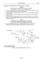
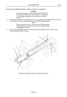
Route ends of speed sensor harness (figure 84, item 1) and modulator harness (figure 84, item 2) to left-
front, right-front, left-rear, and right-rear locations as depicted in figure 84 below.
NOTE
When securing harnesses, it is necessary to loop back excess length
of wiring and secure it with tie straps. Do not cut and splice harness
wiring together to shorten it.
34.
Secure sensor harness (figure 84, item 1) and modulator harness (figure 84, item 2) with tie straps
during installation along chassis frame.
Figure 84. Routing Speed Sensor and Modulator Harnesses.
Back to Top


