TM-9-2320-283-13-P - Page 158 of 400
0018-56
TM 9-2320-283-13&P
0018
1
2
27.
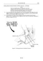
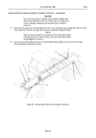
Close center control panel (figure 81, item 2) and turn two turnlock fasteners (figure 81, item 1)
90 degrees.
1
2
3
4
INSTALLATION OF ABS ELECTRONIC CONTROL UNIT (ECU) – CONTINUED
NOTE
The purple wire from circuit 40 to cigar lighter (not in use) is used to
power ABS. The purple wire is located in dash panel wiring harness
behind instrument panel near steering column.
25.
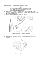
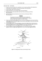
Working under dash panel (figure 80, item 3), locate circuit 40 purple wire (figure 80, item 2), and
connect 36 in. (91 cm) 30-amp fused red wire (figure 80, item 4) to purple wire (figure 80, item 2) with
wire connector (figure 80, item 1).
26.
Secure all ABS ECU harness wires with tie straps where necessary.
Figure 80. Connecting ABS ECU Harness to Battery Power.
Figure 81. Securing Center Control Panel.
Back to Top


