TM-9-2320-283-13-P - Page 163 of 400
0018-61
TM 9-2320-283-13&P
0018
1
2
3
4
5
6
7
INSTALLATION OF ABS ELECTRONIC CONTROL UNIT (ECU) – CONTINUED
38.
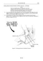
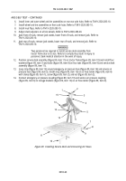
Connect plug (figure 87, item 2) from wheel sensor cable (figure 87, item 1) to harness receptacle
connector (figure 87, item 3) on wheel sensor harness (figure 87, item 4).
39.
Connect plug (figure 87, item 6) from modulator harness (figure 87, item 5) to modulator receptacle
(figure 87, item 7).
40.
Secure loose wheel sensor cable (figure 87, item 1) to brake hose or tube assembly with tie straps.
41.
Repeat steps 37 through 40 to connect and secure remaining three wheel sensor cables and modulators.
Figure 87. Connecting Harness Leads to Wheel Sensor Cable and Modulator.
END OF TASK
Back to Top


