TM-9-2320-283-13-P - Page 172 of 400
TM 9-2320-283-13&P
0019
0019-6
INSTALLATION – CONTINUED
13.
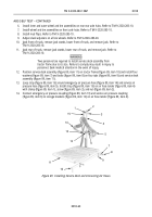
Push in wheel sensor (figure 7, item 7) until it contacts tone ring (figure 7, item 6).
WARNING
Retaining springs may fly out with extreme force during removal
of brake shoes. Wear eye protection when removing brake shoes.
Failure to comply may result in injury to personnel. Seek medical
attention in the event of an injury.
14.
Position upper and lower brake shoes (figure 7, Items 1 and 3) on brake spider (figure 7, item 9)
with two shoe retaining springs (figure 7, item 2) connected.
CAUTION
Ensure hook ends of brake shoe release spring are positioned in
outer grove of pin on brake shoes to provide clearance for tone
ring. Failure to comply may result in damage to equipment.
15.
Secure upper and lower brake shoes (figure 7, Items 1 and 3) at camshaft (figure 7, item 8) by
connecting hook ends of shoe release spring (figure 7, item 5) to pin (figure 7, item 4) on upper and
lower brake shoes (figure 7, Items 1 and 3).
16.
Using suitable pry bar, lift upper brake shoe (figure 7, item 1) at camshaft (figure 7, item 8), and
position roller (figure 7, item 10) and shoulder pin (figure 7, item 11) between upper brake shoe
(figure 7, item 1) and camshaft (figure 7, item 8).
17.
Repeat step 16 to install roller (figure 7, item 10) and shoulder pin (figure 7, item 11) on lower
brake shoe (figure 7, item 3).
18.
Install front brake drum. Refer to TM 9-2320-283-20.
1
2
3
4
5
6
6
1
7
8
9
10
3
4
11
5
Figure 7. Positioning Wheel Sensor and Installing Brake Shoes.
END OF TASK
END OF WORK PACKAGE
Back to Top


