TM-9-2320-283-13-P - Page 162 of 400
0018-60
TM 9-2320-283-13&P
0018
1
2
3
4
2
5
1
2
3
INSTALLATION OF ABS ELECTRONIC CONTROL UNIT (ECU) – CONTINUED
NOTE
Each wheel sensor harness lead comes with two wire connectors for
connecting harness leads to sensor cable. Wire connectors shall be
crimped and heat shrunk during installation.
35.
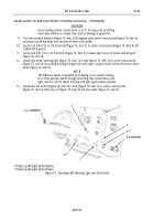
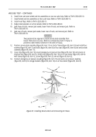
Connect harness brown wire (figure 85, item 5) to sensor cable white wire (figure 85, item 4) and
harness black wire (figure 85, item 1) to sensor cable black wire (figure 85, item 3) using two new wire
connectors (figure 85, item 2). Wrap wire connectors (figure 85, item 2) with electrical tape.
36.
Repeat step 35 to connect remaining three wheel sensor harness leads to sensor cables.
Figure 85. Connecting Harness Leads to Wheel Sensor Cable Leads.
NOTE
Connecting harness leads to wheel sensor cables and modulators is
performed the same way. Left-rear modulator and wheel sensor cable
is shown.
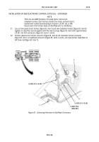
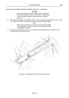
37.
Route wheel sensor cable (figure 86, item 2) up to frame rail (figure 86, item 3) and behind left-rear
modulator mounting bracket (figure 86, item 1).
Figure 86. Routing Wheel Sensor Cable.
Back to Top


