TM-9-2320-283-13-P - Page 159 of 400
0018-57
TM 9-2320-283-13&P
0018
1
2
3
4
5
6
7
8
9
10
~
28.
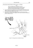
Position circuit breaker panel (figure 82, item 4) in place on dash panel (figure 82, item 9) and install
star washer (figure 82, item 3) and screw (figure 82, item 2) on dash panel (figure 82, item 9) and circuit
breaker panel (figure 82, item 4).
29.
From glove compartment (figure 82, item 8), install two star washers (figure 82, item 6) and screws
(figure 82, item 7) on dash panel (figure 82, item 9) and circuit breaker panel (figure 82, item 4). Close
and secure glove compartment door (figure 82, item 10).
30.
Close circuit breaker cover (figure 82, item 1) and turn three turnlock fasteners (figure 82, item 5)
90 degrees.
Figure 82. Securing Center Control Panel.
INSTALLATION OF ABS ELECTRONIC CONTROL UNIT (ECU) – CONTINUED
Back to Top


