TM-9-2320-283-13-P - Page 149 of 400
0018-47
TM 9-2320-283-13&P
0018
1
2 (PH1220-8B-RED100)
3 (W1468X8)
4
5
1
2
3
4 (9419871)
5
6
7 (W1480X8)
8
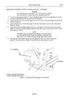
INSTALLATION OF ABS AIR LINES – CONTINUED
Figure 68. Installing Tube on Quick-Release Valve.
NOTE
The mountable tee, screw, and plug previously removed from right
frame rail adjacent to quick-release valve is reused in step 73.
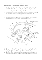
73.
Install elbow (figure 69, item 7) and plug (figure 69, item 3) on mountable tee (figure 69, item 2), and
install mountable tee (figure 69, item 2) on top hole in right frame rail (figure 69, item 6) with new
lockwasher (figure 69, item 4) and screw (figure 69, item 5).
74.
Connect 1/2 in. (13 mm) red tube (figure 69, item 8) from quick-release valve (figure, 68 item 4) to
elbow (figure 69, item 7), and install hose assembly (figure 69, item 1) on mountable tee
(figure 69, item 2).
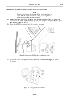
Figure 69. Installing Mountable Tee on Right Frame Rail.
Back to Top


