TM-9-2320-283-13-P - Page 148 of 400
0018-46
TM 9-2320-283-13&P
0018
1
2
3
4
5 (W411008)
6
*
7
*
8
9
INSTALLATION OF ABS AIR LINES – CONTINUED
NOTE
Ensure spring brake chamber is installed so mounting studs are at top
of elongated holes in camshaft bracket prior to tightening locknuts.
68.
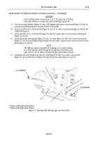
Install spring brake chamber (figure 67, item 1) on camshaft bracket (figure 67, item 8) with two
washers (figure 67, item 7) and new locknuts (figure 67, item 6) supplied with spring brake chamber
(figure 67, item 1).
69.
Connect clevis (figure 67, item 2) to slack adjuster (figure 67, item 3) with pin (figure 67, item 4) and
new cotter pin (figure 67, item 5). Tighten jamnut (figure 67, item 9). Un-cage spring brake chamber
(figure 67, item 1). Refer to TM 9-2320-283-10.
70.
Repeat steps 62 through 69 for installation of opposite spring brake chamber (figure 67, item 1).
*
ITEM 6 SUPPLIED WITH ITEM 1
*
ITEM 7 SUPPLIED WITH ITEM 1
Figure 67. Installing Spring Brake Chambers.
71.
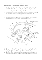
Remove plug (figure 68, item 1) from quick-release valve (figure 68, item 4) on right frame rail
(figure 68, item 5), and install new adapter (figure 68, item 3) on quick-release valve (figure 68, item 4).
72.
Cut and route new piece of 1/2 in. (13 mm) red tubing (figure 68, item 2) 80 in. (203 cm) in length on
right frame rail (figure 68, item 5), and connect end of tube (figure 68, item 2) to adapter
(figure 68, item 3) on quick-release valve (figure 68, item 4).
Back to Top


