TM-9-2320-283-13-P - Page 153 of 400
0018-51
TM 9-2320-283-13&P
0018
~
1
2
3
3
4
INSTALLATION OF ABS ELECTRONIC CONTROL UNIT (ECU)
1.
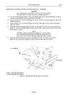
Working inside cab left of steering column, position T1 template (supplied in ABS kit) over two studs
(figure 73, item 1), and mark location of four holes (figure 73, item 3) and two holes (figure 73, item 4)
on cab firewall (figure 73, item 2). Remove T1 template.
2.
Drill four 3/16 in. (5 mm) holes (figure 73, item 3) and two 1-1/2 in. (38 mm) holes (figure 73, item 4)
through cab firewall (figure 73, item 2).
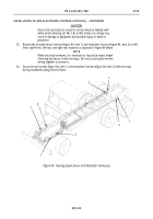
Figure 73. Drilling Holes for ABS ECU and Bulkhead Connectors.
1
2
3 (JG-55287-D)
4
5
6
*
7
*
~
3.
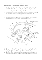
Working outside cab, cut and remove exterior insulation (figure 74, item 1) from around holes
(figure 74, items 2 and 4) drilled in firewall (figure 74, item 5).
CAUTION
Plastic bulkhead nuts shall be finger tightened on bulkhead
connectors. Over tightening plastic nut will strip threads and damage
bulkhead.
NOTE
Assistant will help with installation of harness bulkhead connectors.
4.
Install new ABS ECU harness bulkhead connector (figure 74, item 3) on hole (figure 74, item 2) closest
to steering column with washer (figure 74, item 7) and nut (figure 74, item 6) supplied with new
connector (figure 74, item 3).
5.
Repeat step 7 for installation of opposite bulkhead connector on hole (figure 74, item 4).
*
ITEM 6 SUPPLIED WITH ITEM 3
*
ITEM 7 SUPPLIED WITH ITEM 3
Figure 74. Installing Electrical Bulkhead Connectors.
Back to Top


