TM-9-2320-283-13-P - Page 155 of 400
0018-53
TM 9-2320-283-13&P
0018
1 (L1-AMBER)
2
3
4
5
*
6 (CHS9095)
7
8
*
INSTALLATION OF ABS ELECTRONIC CONTROL UNIT (ECU) – CONTINUED
CAUTION
Ensure wiring behind control panel is not in the way prior to drilling
new holes. Failure to comply may result in damage to equipment.
9.
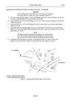
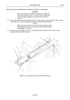
Turn two turnlock fasteners (figure 76, item 3) 90 degrees, open center control panel (figure 76, item 4),
and move any wiring away from location of holes to be drilled.
10.
Locate and drill 9/16 in. (14 mm) hole (figure 76, item 2) in center control panel (figure 76, item 4) left
of BEACON switch.
11.
Locate and drill 1/2 in. (13 mm) hole (figure 76, item 7) in lower right corner of center control panel
(figure 76, item 4).
12.
Install new amber warning light (figure 76, item 1) in hole (figure 76, item 2) on center control panel
(figure 76, item 4) by pushing housing through hole until collar is against front surface of center control
panel (figure 76, item 4).
NOTE
The ABS test switch is installed by threading nut on switch housing
first. Then position switch through mounting hole, install collar until
tight, and turn nut on switch housing until tight against back of panel.
13.
Install new test switch (figure 76, item 6) in hole (figure 76, item 7) on center control panel
(figure 76, item 4) with new nut (figure 76, item 5) and new collar (figure 76, item 8).
*
ITEM 5 SUPPLIED WITH ITEM 6
*
ITEM 8 SUPPLIED WITH ITEM 6
Figure 76. Installing ABS Warning Light and Test Switch.
Back to Top


