TM-9-2320-283-13-P - Page 156 of 400
0018-54
TM 9-2320-283-13&P
0018
18.
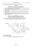
Turn three turnlock fasteners 90 degrees, and hinge open circuit breaker cover (figure 78, item 8).
19.
Open glove compartment door (figure 78, item 7), and remove two screws (figure 78, item 5) and star
washers (figure 78, item 4) from dash panel (figure 78, item 6) and circuit breaker panel
(figure 78, item 3).
20.
Remove screw (figure 78, item 1) and star washer (figure 78, item 2) from dash panel (figure 78, item 6) and
circuit breaker panel (figure 78, item 3), and lift circuit breaker panel (figure 78, item 3) out to access wiring.
1
2
3
4
5 (J1128-GPT-12-BLACK)
6
7
8
10
9
11 (GPT 12
AWG BLUE)
17
16
15
14
13
12
INSTALLATION OF ABS ELECTRONIC CONTROL UNIT (ECU) – CONTINUED
14.
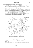
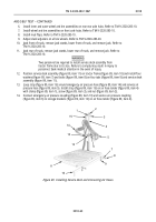
Route 76 in. (193 cm) blue wire (figure 77, item 10) from ABS ECU harness to test switch
(figure 77, item 16), and connect blue wire (figure 77, item 10) and black wire (figure 77, item 2) to
terminal (figure 77, item 17) with star washer (figure 77, item 7) and screw (figure 77, item 6).
15.
Connect new 8 in. (203 mm) black wire (figure 77, item 11) to test switch terminal (figure 77, item 15)
with star washer (figure 77, item 9) and screw (figure 77, item 8).
16.
Remove nut (figure 77, item 12) and star washer (figure 77, item 13) from heater control box mounting
stud (figure 77, item 14), and connect opposite end of 8 in. (203 mm) black wire (figure 77, item 11) to
stud (figure 77, item 14) with star washer (figure 77, item 13) and nut (figure 77, item 12).
NOTE
Wire connectors shall be crimped and heat shrunk during installation.
17.
Connect remaining black wire (figure 77, item 3) from warning light (figure 77, item 1) to new 36 in.
(91 cm) blue wire (figure 77, item 5) with new wire connector (figure 77, item 4).
Figure 77. Connecting ABS Warning Light and Test Switch.
Back to Top


