TM-9-2320-283-13-P - Page 165 of 400
0018-63
TM 9-2320-283-13&P
0018
1
2
3
4
5
6
7
8
9
10
11
12
13
14
15
ABS SELF TEST – CONTINUED
6.
Install inner and outer wheel and tire assemblies on rear-rear axle hubs. Refer to TM 9-2320-283-10.
7.
Install wheel and tire assemblies on front axle hubs. Refer to TM 9-2320-283-10.
8.
Install mud flaps. Refer to TM 9-2320-283-10.
9.
Adjust slack adjusters on all six wheels. Refer to TM 9-2320-283-20.
10.
Jack front of truck, remove jack stands, lower front of truck, and remove jack. Refer to
TM 9-2320-283-10.
11.
Jack rear of truck, remove jack stands, lower rear of truck, and remove jack. Refer to
TM 9-2320-283-10.
WARNING
Two personnel are required to install service deck assembly from
tractor frame due to its size. Failure to comply may result in injury to
personnel. Seek medical attention in the event of injury.
12.
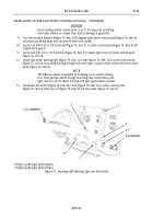
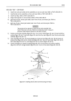
Position service deck assembly (figure 89, item 11) on tractor frame (figure 89, item 10) and install four
washers (figure 89, item 7) and bolts (figure 89, item 8) on four tabs (figure 89, item 9) and service deck
assembly (figure 89, item 11).
13.
Loop strap (figure 89, item 15) around emergency air pressure hose (figure 89, item 14) and service air
pressure hose (figure 89, item 5). Install strap (figure 89, item 15) on air hose tender (figure 89, item 4)
with clamp (figure 89, item 1), screw (figure 89, item 3), and nut (figure 89, item 2).
14.
Connect emergency air pressure coupling (figure 89, item 13) and service air pressure coupling
(figure 89, item 6) to storage brackets (figure 89, item 12) on air hose tender (figure 89, item 4).
Figure 89. Installing Service Deck and Connecting Air Hoses.
Back to Top

