TM-9-2320-283-13-P - Page 171 of 400
TM 9-2320-283-13&P
0019
0019-5
1
2
3
4
5
6
7
8
9
10
INSTALLATION – CONTINUED
8.
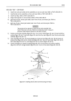
Fill cavity of front hub (figure 6, item 2) with grease and carefully position hub (figure 6, item 2) on
spindle (figure 6, item 1).
9.
Apply grease to outer bearing cone (figure 6, item 3) and position bearing cone (figure 6, item 3) on
spindle (figure 6, item 1) against outer cup of front hub (figure 6, item 2).
10.
Install key washer (figure 6, item 4) and slotted nut (figure 6, item 5) on spindle (figure 6, item 1) and
using 2-1/4 in. (57 mm) socket, tighten slotted nut (figure 6, item 5) to 50 lb-ft (68 N•m). Back off
slotted nut (figure 6, item 5) 1/4 to 1/3 turn until hole in spindle and slot in nut line up. Rotate hub; hub
should rotate freely.
11.
Insert new cotter pin (figure 6, item 6) through slotted nut (figure 6, item 5) and hole in spindle
(figure 6, item 1). Bend ends of cotter pin (figure 6, item 6) over slotted nut (figure 6, item 5) and into
hole in center of spindle.
NOTE
Front bearings and hub are packed with grease during installation.
Front hub shall not be filled with oil.
12.
Install new gasket (figure 6, item 10) and cap (figure 6, item 7) on front hub (figure 6, item 2) with six
new lockwashers (figure 6, item 9) and bolts (figure 6, item 8).
Figure 6. Installing Front Wheel Hub.
Back to Top


