TM-9-2320-283-13-P - Page 157 of 400
0018-55
TM 9-2320-283-13&P
0018
1
2
3
4
5
6
7
8
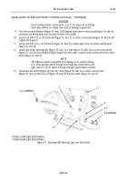
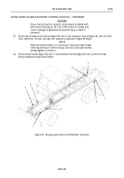
Figure 78. Removing Circuit Breaker Panel.
21.
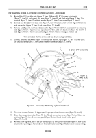
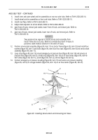
Route 36 in. (91 cm) blue wire (figure 79, item 6) from ABS warning light to circuit breaker panel
(figure 79, item 2).
NOTE
Circuit 38 terminal stud has two green wires connected to it.
22.
Remove nut (figure 79, item 5) from CB#3, circuit 38, terminal stud (figure 79, item 7), and connect 36
in. (91 cm) blue wire (figure 79, item 6) to terminal stud (figure 79, item 7) with nut
(figure 79, item 5).
23.
Route 102 in. (91 cm) 5-amp fused orange wire (figure 79, item 4) from ECU harness to circuit breaker
panel (figure 79, item 2).
NOTE
Circuit 12C terminal stud has a bus bar and one red wire connected
to it.
24.
Remove nut (figure 79, item 3) from CB#3, circuit 12C, terminal stud (figure 79, item 1), and connect
orange wire (figure 79, item 4) to terminal stud (figure 79, item 1) with nut (figure 79, item 3).
INSTALLATION OF ABS ELECTRONIC CONTROL UNIT (ECU) – CONTINUED
1
2
3
4
5
6
7
Figure 79. Connecting ABS ECU Harness to CB#3.
Back to Top


