TM-9-2320-283-13-P - Page 129 of 400
0018-27
TM 9-2320-283-13&P
0018
1
2 (W373804)
3 (W343804)
4
5 (W1480X8X8)
6
7 (W373804)
8 (W380428)
9
10
1
2
3
4
5 (W1468X8X8
6 (BW801481)
INSTALLATION OF FRONT MODULATORS – CONTINUED
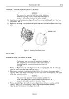
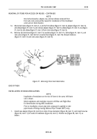
Figure 40. Drilling Mounting Holes for Front Modulator.
5.
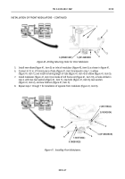
Install new elbow (figure 41, item 5) on inlet of modulator (figure 40, item 6) as shown in figure 41.
6.
Connect 4-1/2 in. (114 mm) piece of tube (figure 41, item 9) removed in step 1, to elbow
(figure 41, item 1), and install remaining length of tube (figure 41, item 4) on elbow (figure 41, item 5).
7.
Install modulator (figure 41, item 6) on inside of left frame rail (figure 41, item 10), at holes drilled in
step 4, with two new washers (figure 41, item 7), new bolts (figure 41, item 8), new washers
(figure 41, item 2), and new locknuts (figure 41, item 3).
8.
Repeat steps 1 through 7 for installation of opposite front modulator (figure 41, item 6).
Figure 41. Installing Front Modulators.
Back to Top


