TM-9-2330-342-23-P - Page 487 of 1348
TYPE 1 CONNECTOR REPAIR - Continued
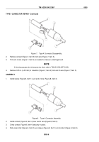
4.
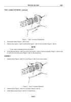
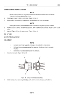
Slide plastic sleeve (Figure 2, Item 6) against connector (Figure 2, Item 3).
5.
Install cover (Figure 2, Item 1) on connector (Figure 2, Item 3).
END OF TASK
TYPE 2 CONNECTOR REPAIR
CAUTION
Terminals come in different styles and sizes. To prevent damage, be sure to use only the
exact replacements. Do not attempt to modify terminal to fit.
NOTE
Repeat procedure as necessary.
DISASSEMBLY
1.
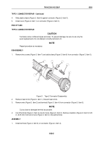
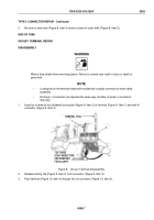
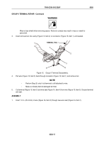
Remove two screws (Figure 3, Item 7) and cable clamp (Figure 3, Item 6) from connector (Figure 3, Item 5).
1
2
3
4
5
6
7
Figure 3.
Type 2 Connector Disassembly.
2.
Remove heat shrink (Figure 3, Item 1). Discard heat shrink.
3.
Remove wire (Figure 3, Item 2) and terminal (Figure 3, Item 4) from connector (Figure 3, Item 5).
NOTE
Cut as close to damaged terminal as possible.
4.
Cut off terminal (Figure 3, Item 4) at end of wire (Figure 3, Item 2). Remove insulation (Figure 3, Item 3) 0.25
in. (6.35 mm) from end of wire (Figure 3, Item 2). Discard terminal.
ASSEMBLY
1.
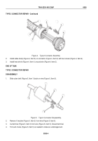
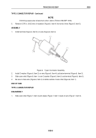
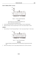
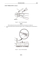
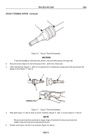
Install terminal (Figure 4, Item 3) on connector (Figure 4, Item 4).
TM 9-2330-342-23&P
0055
0055-3
Back to Top

