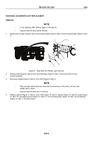
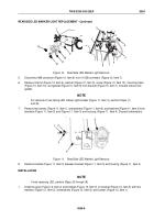
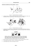
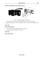
TM-9-2330-342-23-P - Page 490 of 1348
TYPE 4 CONNECTOR REPAIR - Continued
1
2
4
3
5
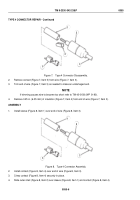
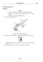
Figure 7.
Type 4 Connector Disassembly.
2.
Remove contact (Figure 7, Item 5) from wire (Figure 7, Item 3).
3.
Trim end of wire (Figure 7, Item 3) as needed to make an undamaged end.
NOTE
If trimming causes wire to become too short refer to TM 43-0158 (WP
0190).
4.
Remove 0.25 in. (6.35 mm) of insulation (Figure 7, Item 4) from end of wire (Figure 7, Item 3).
ASSEMBLY
1.
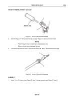
Install sleeve (Figure 8, Item 1) over end of wire (Figure 8, Item 3).
1
2
3
4
Figure 8.
Type 4 Connector Assembly.
2.
Install contact (Figure 8, Item 4) over end of wire (Figure 8, Item 3).
3.
Crimp contact (Figure 8, Item 4) securely in place.
4.
Slide outer shell (Figure 8, Item 2) over sleeve (Figure 8, Item 1) and contact (Figure 8, Item 4).
TM 9-2330-342-23&P
0055
0055-6
Back to Top

