TM-9-2330-342-23-P - Page 489 of 1348
TYPE 3 CONNECTOR REPAIR - Continued
NOTE
If trimming causes wire to become to short, refer to TM 43-0158 (WP
0190).
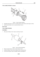
5.
Remove 0.375 in. (9.52 mm) of insulation (Figure 5, Item 4) from end of wire (Figure 5, Item 5).
ASSEMBLY
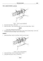
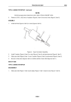
1.
Install terminal (Figure 6, Item 3) on wire (Figure 6, Item 4).
1
2
3
4
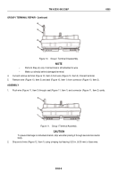
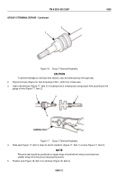
Figure 6.
Type 3 Connector Assembly.
2.
Install C-washer (Figure 6, Item 2) on wire (Figure 6, Item 4) just below terminal (Figure 6, Item 3).
3.
Slide outer shell (Figure 6, Item 1) over C-washer (Figure 6, Item 2) and terminal (Figure 6, Item 3).
4.
Be sure no bare wire (Figure 6, Item 4) is visible outside of outer shell (Figure 6, Item 1).
END OF TASK
TYPE 4 CONNECTOR REPAIR
DISASSEMBLY
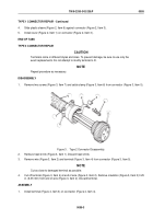
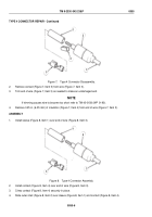
1.
Slide outer shell (Figure 7, Item 2) and sleeve (Figure 7, Item 1) back on wire (Figure 7, Item 3).
TM 9-2330-342-23&P
0055
0055-5
Back to Top

