TM-9-2330-342-23-P - Page 494 of 1348
GROUP I TERMINAL REPAIR - Continued
NOTE
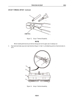
Wire should be positioned so larger wings of terminal will crimp around insulation and smaller
wings will crimp around exposed bare wire.
4.
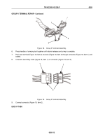
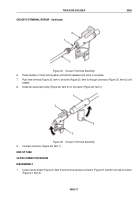
Position wire (Figure 13, Item 2) on terminal (Figure 13, Item 1).
5.
Press handle(s) of crimping tool together until ratchet releases and crimp is complete.
NOTE
Locking tab should be positioned toward notch in connector cavity when properly installed.
6.
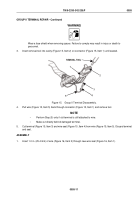
Pull wire (Figure 13, Item 2) and terminal (Figure 13, Item 1) back through connector (Figure 13, Item 4) until
sealed.
7.
Seat seal (Figure 13, Item 3) into connector (Figure 13, Item 4).
END OF TASK
GROUP II TERMINAL REPAIR
DISASSEMBLY
NOTE
•
Connector is removed by gently prying up on clip and pulling on connector.
•
All Group II connectors are repaired the same way. Number of wires in connector
may vary.
•
Both halves of connector are repaired the same way.
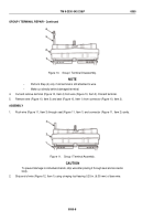
1.
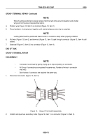
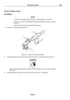
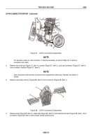
Disconnect connector (Figure 14, Item 2).
1
1
2
2
Figure 14.
Group II Terminal Disassembly.
2.
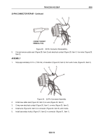
Unlatch and open two secondary locks (Figure 14, Item 1) on connector (Figure 14, Item 2).
TM 9-2330-342-23&P
0055
0055-10
Back to Top


