TM-9-2330-342-23-P - Page 491 of 1348
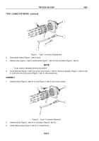
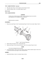
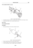
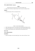
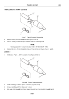
TYPE 4 CONNECTOR REPAIR - Continued
5.
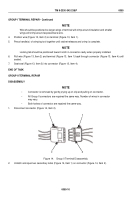
Be sure no bare wire (Figure 8, Item 3) shows outside of outer shell (Figure 8, Item 2).
END OF TASK
GROUP I TERMINAL REPAIR
DISASSEMBLY
WARNING
Wear a face shield when removing spacer. Failure to comply may result in injury or death to
personnel.
NOTE
•
Locking tab on the terminal mates with molded tab in plastic connector to retain cable
assembly.
•
All Group 1 connectors are repaired the same way. Number of wires in connection
may vary.
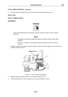
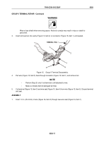
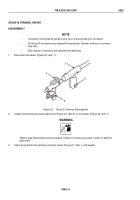
1.
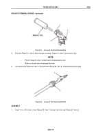
Insert tip of removal tool between locking tab (Figure 9, Item 2) of terminal (Figure 9, Item 1) and wall of
connector (Figure 9, Item 3).
2
3
TOP THREE
ECM CONNECTORS
ARE REMOVED
FOR CLARITY
1
REMOVAL TOOL
Figure 9.
Group I Terminal Disassembly.
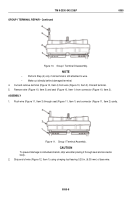
2.
Release locking tab (Figure 9, Item 2) from connector (Figure 9, Item 3).
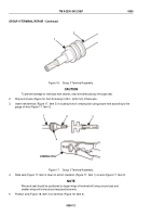
3.
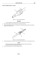
Push terminal (Figure 10, Item 4) through front of connector (Figure 10, Item 2).
TM 9-2330-342-23&P
0055
0055-7
Back to Top

