TM-9-2350-260-20-1-3 - Page 522 of 783
TM 9-2350-260-20-1-3
UNIVERSAL JOINT REPLACEMENT (Sheet 4.1 of 7)
NOTE
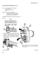
4.
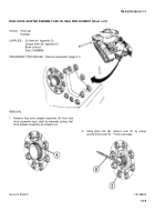
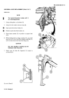
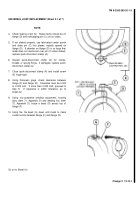
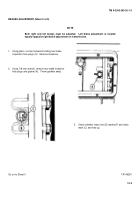
Check staking of pin (C).
Stake marks should be on
flange (D) and overlapping pin (C) on four sides.
5.
If not staked properly, use fabricated center punch
and stake pin (C) four places, equally spaced on
flange (D).
If chamfer on flange (D) is so large that
metal does not mushroom over pin (C) when staked,
replace quick-disconnect clamp (A).
6.
Inspect quick-disconnect clamp (A) for cracks,
breaks, or sprung hinge.
If damaged, replace quick-
disconnect clamp (A).
7.
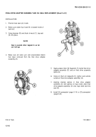
Close quick-disconnect clamp (A) and install screw
(E) finger tight.
8.
Using thickness gage, check clearance between
flange (F) and flange (D).
Clearance must be 0.000
to 0.005 inch.
If more than 0.005 inch, proceed to
step 9.
If clearance is within tolerance, go to
sheet 4.2.
9.
Using oxy-acetylene welding equipment, brazing
alloy (Item 71, Appendix D) and welding flux (Item
72, Appendix D), braze a bead (G) across top of
flange (F).
10. Using file, file bead (G) down until metal to metal
contact exists between flange (F) and flange (D).
Go on to Sheet 4.2
Change 2
12-14.1
Back to Top

