TM-9-2815-205-34 - Page 205 of 596
TM 9-2815-205-34
3-23. FUEL PUMP REPLACEMENT
This task covers:
a. Removal
b. Disassembly
c. Cleaning/Inspection
d. Assembly
e. Installation
INITIAL SETUP
MODELS
EXPENDABLE/DURABLE SUPPLIES
All
Oil, fuel (App C, Item 27)
Oil, engine (App C, Item 26)
TOOLS AND SPECIAL TOOLS
Sealing compound (App C, Item 44)
Tool kit, general mechanics (App B, Item 107)
Shortening compound (App C, Item 47)
Wrench, torque (App B, Item 116)
Wrench, torque (App B, Item 118)
EQUIPMENT CONDITION
Tool set, fuel pump (App B, Item 109)
Para
Installer, oil seal
3-17
Remover, oil seal
3-18
Adapter, oil seal
Vise, machinist (App B, Item 111)
3-19
Caps
l
vise jaw (App B, Item 13)
MATERIALS/PARTS
1
Gasket (App F, Item 72)
Gasket (App F, Item 73)
2
Seals, plain encased (App F, Item 170)
Description
Fuel lines removed (model 5063-5392)
Fuel lines removed (models 5063-5393
and 5063-539L)
Fuel lines removed (models 5063-5395,
5063-5398, and 5063-539F)
a. Removal
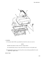
(1) Remove three bolts (1), fuel pump (2), and
gasket (3) from flywheel housing. Discard
gasket.
(2) Remove drive coupling fork (4) from drive
adapter (5).
b. Disassembly
(1) Place fuel pump (2) in a soft-jawed vise.
Remove elbows (6 and 7) from pump.
(2) Remove eight bolt and lockwasher
assemblies (8) and pump body cover (9)
from pump body (10).
(3) Remove drive shaft assembly (11) from
(4)
3-76
pump body (10).
NOT E
Driven gear is an assembly. Do
not remove gear from shaft.
Remove driven gear assembly (12) from
pump body (10).
Change 1
Back to Top


