TM-9-2815-205-34 - Page 208 of 596
TM 9-2815-205-34
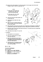
(12) Lubricate drive shaft assembly (11) with clean engine oil. Insert square end of drive shaft
through oil seals (21 and 22) in pump body (10).
(13)
(14)
(15)
(16)
(17)
(18)
NOT E
If gear teeth of driven gear have
a chamfered end, install cham-
fered end facing pump body.
If driven gear has a slot, install
gear with slot facing cover.
Install driven gear and shaft assembly (12)
in pump body (10).
Lubricate gears and shafts with clean
engine oil.
Apply a thin coat of sealing compound on
cover (9) surface. Do not allow compound
to enter gear chamber.
Align pump body (10) and cover (9). Install cover and eight bolt and Iockwasher assemblies (8)
on pump body. Tighten bolts alternately and evenly. Torque bolts to 84-108 lb-in (10-12 N•m).
Rotate drive shaft (14) by hand, Shaft should rotate freely. If not, gently tap corner of pump body
(10) with hammer to free up.
Install elbow (6) and elbow (7) in cover (9).
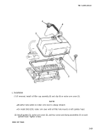
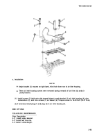
e. Installation
(1)
(2)
(3)
(4)
Install gasket (3) on fuel pump (2).
Place drive coupling fork (4) on square
end of drive shaft (14).
Align drive coupling fork (4) with slots in
drive adapter (5) and install fuel pump (2)
on flywheel housing with fuel inlet hole in
down and inboard position.
Install three bolts (1) fastening fuel pump
(2) to flywheel housing. Torque bolts to
13-17 Ib-ft (18-23 NŽm).
END OF TASK
FOLLOW-ON MAINTENANCE
Para
3-17
3-18
3-19
Description
Install fuel lines (model 5063-5392).
Install fuel lines (models 5063-5393 and
5063-539L).
Install fuel lines (models 5063-5395,
5063-5398, and 5063-539F).
Change 1
3-79
Back to Top


