TM-9-2815-205-34 - Page 207 of 596
TM 9-2815-205-34
3-23. FUEL PUMP REPLACEMENT (Cont)
d. Assembly
(1)
(2)
(3)
(4)
(5)
(6)
(7)
(8)
(9)
(10)
(11)
3-78
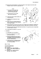
Lubricate oil seals (21 and 22) with a thin
coat of shortening compound.
NOT E
Install new oil seals with seal
lips facing each other as
shown.
Support pump body (10) on wood blocks.
Using oil seal installer (25), drive inner oil
seal (21) into pump body until it bottoms
out.
Using oil seal adapter (26) and installer
(25), drive outer seal (22) into pump body
(10) until shoulder on adapter contacts
pump body.
Clamp pump body (10) in soft-jawed vise.
Lubricate outside diameter of relief valve
(20) with clean engine oil. Insert valve into
pump body (10) with hollow end facing
Install spring (18) and straight pin (19)
into relief valve (20).
Install gasket (17) on plug (16) and screw
into pump body (10). Torque plug to
18-22 Ib-ft (24-30 N-m).
If removed, install two pipe plugs (23) in
upper drain holes of pump body (10).
If removed, install two straight pins (24)
into cover (9). Press pins into inner face
of cover until they are flush with outer
face.
NOT E
Install drive gear with slot fac-
ing round end of drive shaft.
If removed, install drive gear (13) on
round end of drive shaft (14). Press drive
gear beyond locking ball (15) detent on
drive shaft.
Install locking ball (15) into drive shaft (14) detent. Invert drive shaft and press drive gear
until end of slot in gear contacts locking ball.
(13)
out.
Back to Top


