TM-9-2815-205-34 - Page 210 of 596
TM 9-2815-205-34
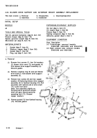
(1) Clean air inlet housing and adapter with cleaning solvent and dry with compressed air.
(2) Inspect parts for wear or damage.
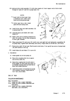
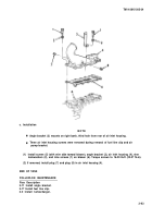
(1) Place air inlet screen (13) on top of blower (3) with wire side to blower.
(2) Install air inlet housing (2), five flat washers (12), five Iockwashers (11), two long screws (8),
short screw (9), and two mid-sized screws (10) on blower (3) with inlet opening on left side of
engine. Torque bolts to 16-20 Ib-ft (22-27 N-m).
(3) Install gasket (7) and air inlet adapter (1) on air inlet housing (2) with adapter opening toward
rear of engine. Align scribe marks on air inlet housing and adapter. Install four flat washers (6),
four Iockwashers (5), and four screws (4). Torque bolts to 16-20 Ib-ft (22-27 N
.
m).
END OF TASK
FOLLOW-ON MAINTENANCE
Para Description
3-16 Install fuel line clip.
3-10 Connect airbox heater air line to air inlet elbow.
3-81
c. Installation
Back to Top


