TM-9-2815-205-34 - Page 219 of 596
TM 9-2815-205-34
3-30. BLOWER DRIVE SUPPORT AND GOVERNOR WEIGHT ASSEMBLY REPLACEMENT
This task covers: a. Removal
b. Disassembly
c. Cleaning/Inspection
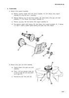
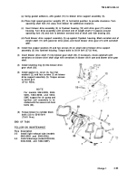
d. Assembly
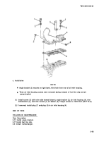
e. Installation
INITIAL SETUP
MODELS
All
TOOLS AND SPECIAL TOOLS
Tool kit, general mechanics (App B, Item 107)
Wrench, torque (App B, Item 116)
Spacer, governor weight (App B, Item 94)
Micrometer set (App B, Item 73)
MATERIALS/PARTS
Gasket (App F, Item 51)
Washers, copper (App F, Item 186)
Gasket (App F, Item 30)
Plug, cup (App F, Item 127)
EXPENDABLE/DURABLE SUPPLIES
Oil, fuel (App C, Item 27)
Oil, engine (App C, Item 26)
Grease (App C, Item 18)
Sealing compound (App C, Item 44)
Adhesive, gasket (App C, Item 1)
EQUIPMENT CONDITION
Para Description
3-3 Turbocharger removed (models
5063-5395, 5063-5398, and 5063-539F)
3-5 Right exhaust tube removed (models
5063-5393 and 5063-539L)
a. Removal
(1)
(2)
(3)
(4)
3-90
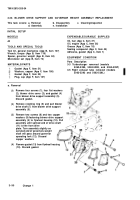
Remove four screws (1), four flat washers
(2), blower drive cover (3), and gasket (4)
from blower drive support assembly (5).
Discard gasket.
Remove retaining ring (6) and pull blower
drive shaft (7) from blower drive support
assembly (5).
Remove two screws (8) and two copper
washers (9) fastening blower drive support
assembly (5) to flywheel housing (10). Pull
assembly until splined end of drive shaft
(11) is free from drive
plate. Turn assembly slightly so
serrated end of governors weight
shaft will pass around governor
operating fork (12). Discard
copper washers.
Remove gasket (13) from flywheel housing
(10). Discard gasket.
Change 1
Back to Top


