TM-9-2815-205-34 - Page 221 of 596
TM 9-2815-205-34
3-30. BLOWER DRIVE SUPPORT AND GOVERNOR WEIGHT ASSEMBLY REPLACEMENT (Cont)
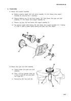
(3) Governor weight shaft and carrier assembly
(a)
(b)
(c)
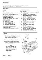
Remove four retaining rings (23) from four weight pins (24).
Drive four weight pins (24) out of carrier assembly (25) by tapping on punch held against
grooved end of pin. Remove two low speed weights (26) and two high speed weights (27).
Press carrier (28) and governor riser assembly (29) from shaft (11).
NOT E
Do not remove bearing from
riser since it is serviced only as
an assembly.
(d) Slide governor riser assembly (29)
from shaft (11).
c. Cleaning/Inspection
(1)
(2)
(3)
(4)
(5)
(6)
(7)
3-92
WARNING
Compressed air used for
exceed 30 PSI. Use only with
effective chip guarding and
personal protective equip-
(goggles/shield,
gloves, etc.)
Wash all parts in fuel oil and dry them
with compressed air.
Inspect all bearings. Revolve ball bearing
slowly by hand and observe rough or tight
spots. Replace if this condition exists.
Replace bearings if corroded or pitted.
Inspect gear teeth for evidence of
scoring, pitting, burning, or wear.
Examine blower drive support thrust
washer for scoring and wear. Thickness
of new thrust washer is 0.093-0.103 inch.
Inspect serrations on blower drive shaft and governor weight shaft. If excessive backlash is felt
when shaft is inserted into mating part, install new shaft.
Inspect outside diameter of blower drive gear shaft and mating inside diameter of drive support
for scoring and wear.
Examine weight carrier, weights, and pins. Replace worn parts.
cleaning purposes will not
ment.
Back to Top


