TM-9-2815-205-34 - Page 227 of 596
TM 9-2815-205-34
3-31. GOVERNOR COVER AND THROTTLE CONTROL RODS REMOVAL/INSTALLATION (Cont)
b. Installation
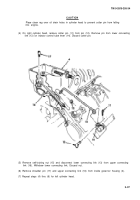
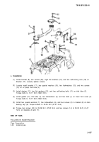
(1) On right cyIinder, install right upper connecting link (16) from inside governor housing (4) and
then install shoulder pin (17). Tighten pin securely.
(2) Connect lower connecting link (13) to upper connecting link (16) with self-locking nut (15).
Tighten nut securely.
(3) Install pin (12) through injector control tube lever (14) and then through lower connecting link
(13) with cotter pin hole toward front. Install cotter pin (11) in hole of pin (12).
(4) Repeat steps (1) thru (3) for left cylinder head.
3-98
Back to Top


