TM-9-2815-205-34 - Page 223 of 596
TM 9-2815-205-34
3-30. BLOWER DRIVE SUPPORT AND GOVERNOR WEIGHT ASSEMBLY REPLACEMENT (Cont)
(2) Blower drive support assembly
(a)
(b)
(c)
(d)
(e)
(f)
(g)
(h)
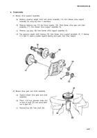
Lubricate drive gear shaft (20) with
engine oil and install in blower drive
support assembly (5).
Install thrust washer (16) and
retaining ring (15) on end of blower
drive gear shaft (20).
Install key (22) in shaft (20).
Support blower drive support
assembly (5). Lubricate inside
diameter of blower drive gear (21)
and start gear straight on shaft (20),
with keyway in gear aligned with key
in shaft. Place governor weight
spacer (32) over gear and press gear
on shaft until there is 0.004 to 0.012
inch clearance between gear and
drive support.
Support blower drive support
assembly (5), with inner face up.
Place governor weight shaft bearing
(19), numbered side up, on bore of
drive support. Using a sleeve against
outer race, press bearing against
shoulder of blower drive support.
Place support under inner race of
governor weight shaft bearing (19).
Start weight end of governor weight
shaft (11) into bearing. Press shaft
until shoulder on shaft contacts inner
race of bearing.
Apply sealing compound to edge of
cup plug (18). Press plug into blower
drive support assembly (5) until flush
with support.
Check clearance between fully extended
Clearance must be greater than 0.100 inch.
governor weights (26 and 27) and drive gear (21).
e. Installation
NOT E
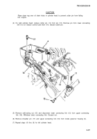
Ensure blower to cylinder block bolts are loose before installing blower drive support.
(1) Install blower drive support assembly to engine as follows:
(a) Using gasket adhesive, affix gasket (13) to blower drive support assembly (5).
3-94
Back to Top


