TM-9-2815-205-34 - Page 229 of 596
TM 9-2815-205-34
3-32. GOVERNOR AND BLOWER ASSEMBLY REMOVAL/INSTALLATION
This task covers: a. Removal
b. Installation
INITIAL SETUP
MODELS
EQUIPMENT CONDITION
All
3-2
TOOLS AND SPECIAL TOOLS
3-19
Tool kit, general mechanics (App B, Item 107)
Wrench, torque (App B, Item 116)
3-10
Sling, (App B, Item 93)
Guide studs (App D, Item 11)
Gage, depth (App B, Item 36)
3-20
Gage set, depth, micrometer (App B, Item 31)
3-21
MATERIALS/PARTS
Gaskets (App F, Item 82)
3-22
Seal, blower App F, Item 163)
F
Gasket (App Item 47)
3-24
Gasket (App F, Item 52)
Lockwashers (App F, Item 99)
3-25
EXPENDABLE/DURABLE SUPPLIES
3-26
Adhesive (App C, Item 1)
International compound no, 2 (App C, Item 21)
3-27
3-30
3-31
a. Removal
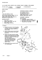
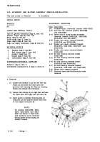
(1)
Loosen two clamps (1) on two left fuel rod
hoses (2) and slide two hoses onto left
governor link housing (3). Remove housing,
hoses, and clamps from left bank.
(2)
Loosen two clamps (4) on right fuel rod hose
(5). Slide hose onto right fuel rod cover (6).
(3)
Insert punch in flywheel housing hole (7)
and drive pin (8) towards blower and clear
of rear engine end plate (9).
NOT E
On models 5063-5299, 5063-
5395, 5063-5398, and 5063-
539F, two blower to block bolts
and washers were removed
during igniter and air pump as-
sembly removal.
Turbocharger removed (model 5063-5392)
Fuel line clip removed (models 5063-5395
and 5063-539F)
Igniter and air pump bracket assembly
removed (models 5063-5299, 5063-5395,
5063-5398, and 5063-539F)
Rocker arm covers removed (models
5063-5299 and 5063-5398)
Rocker arm covers removed (models
5063-5392, 5063-5393, 5063-539F and
5063-539L)
Rocker arm covers removed (model
5063-5395)
Air inlet housing removed (model
5063-5299)
Air inlet housing removed (model
5063-5392)
Air inlet housing removed (model
5063-5393 and 5063-539L)
Air inlet housing removed (models
5063-5395, 5063-5398, and 5063-539F)
Blower drive support removed
Governor cover and throttle control rods
removed
3-100
Change 1
Back to Top

