TM-9-2815-205-34 - Page 224 of 596
TM 9-2815-205-34
(2)
(3)
(4)
(5)
(6)
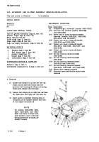
(a) Using gasket adhesive, affix gasket (13) to blower drive support assembly (5).
(b) Place high speed governor weights (27) in horizontal position to provide clearance. Turn
operating shaft fork (12) away from blower for additional clearance.
(c)
Insert blower drive assembly (5) in flywheel housing (10) until drive gear (21) enters
housing. Turn drive assembly until serrated end of weight shaft (11) passes around
operating fork (12) and fork is between serrated end of shaft and riser bearing (30).
(d) Push blower drive support assembly (5) up against flywheel housing. Mesh serrated end of
weight shaft (11) with governor drive plate, and mesh blower drive gear (21) with camshaft
gear.
Install two copper washers (9) and two screws (8) on small end of blower drive support
assembly (5) into flywheel housing. Torque bolts to 20-24 Ib-ft (27-33 N•m).
Insert blower drive shaft (7) into blower gear shaft (20). If necessary, rotate camshaft until
serrations on blower drive shaft align with serrations in blower drive cam and blower drive gear
shaft.
Install retaining ring (6) into blower drive
gear shaft (20).
Install gasket (4), cover (3), four flat
washers (2), and four screws (1) on blower
drive support assembly (5). Torque screws
to 20-24 Ib-ft
(27-33 NŽm).
NOT E
For models 5063-5299, 5063-
5395, 5063-5398, and 5063-
539F, support for air pump and
ignition coil assembly is in-
stalled with the seven-inch front
bolts (33).
Torque blower to cylinder block
bolts (33) to 55-60 Ib-ft
(75-81 N•m).
END OF TASK
FOLLOW-ON MAINTENANCE
Para
3-5
3-3
Description
Install right exhaust tube (models
5063-5393 and 5063-539L).
Install turbocharger (models 5063-5395,
5063-5398, and 5063-539F).
Change 1
3-95
Back to Top


