TM-9-2815-205-34 - Page 232 of 596
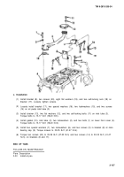
(9)
(10)
(11)
(12)
(13)
Models 5063-52995063-5395,
TM 9-2815-205-34
NOT E
5063-5398, and 5063-539F use two front blower to
block bolts which are 5/16 inch longer. These bolts and washers are installed during the
igniter and air pump assembly installation.
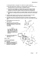
Apply International Compound No. 2, or
equivalent, to four self-locking bolts (10).
Install four hardened washers (11) and
four self-locking bolts, fastening blower to
cylinder block. Finger tighten bolts.
Drive dowel pin (8) into cylinder block rear
end plate (9).
NOT E
Final torquing of bolts, attaching
blower to block, is done follow-
ing blower drive support instal-
lation (Para 3-30).
Torque bolts (10 to 10-15 Ib-ft (14-20
NŽm).
Slide two hoses (2) and two clamps (1)
onto governor link housing (3) and position
between governor and left cylinder head
sleeve (23). Slide hoses and clamps onto
governor housing and cylinder head
sleeve and tighten clamps securely.
Slide hose (5) and two clamps (4) onto
right cylinder head sleeve (24). Tighten
clamps.
END OF TASK
FOLLOW-ON MAINTENANCE
Para
3-31
3-30
3-24
3-25
3-26
3-27
3-20
3-21
3-22
3-10
3-19
3-2
Description
Install governor cover and throttle control rods.
Install blower drive support.
Install air inlet housing (model 5063-5299).
Install air inlet housing (model 5063-5392).
Install air inlet housing (models 5063-5393 and 5063-539L).
Install air inlet housing (models 5063-5395, 5063-5398 and 5063-539F).
Install rocker arm covers (models 5063-5299 and 5063-5398).
Install rocker arm covers (models 5063-5392, 5063-5393, 5063-539F, and 5063-539L).
Install rocker arm covers (model 5063-5395).
Install igniter and air pump bracket assembly (models 5063-5299, 5063-5395, 5063-5398 and
5063-539F).
Install fuel line clip (models 5063-5395 and 5063-539F).
Install turbocharger (model 5063-5392).
Change 1
3-103
Back to Top


