TM-9-2815-205-34 - Page 231 of 596
TM 9-2815-205-34
3-32. GOVERNOR
b. Installation
AND BLOWER ASSEMBLY REMOVAL/INSTALLATION (Cont)
NOT E
•
Remove four bolts and flat washers used to temporarily fasten rear end plate to blower
housing.
•
Insert second screw in right side of governor housing before placing housing on
(1)
(2)
(3)
(4)
(5)
(6)
(7)
(8)
blower.
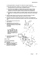
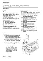
Install gasket (20), governor assembly (16), six flat washers (19), six Iockwashers (18)
screws (17) on blower (21) rear end plate. Torque screws to 20-24 Ib-ft (27-33 N
.
m).
CAUTION
Excessive protrusion of blower
housing with respect to end
plate could cause distortion
when torquing down blower re-
sulting in rotor to housing con-
tact.
Measure distance from bottom of rear
end plate to bottom of blower housing.
Protrusion of blower housing with respect
to end plate must not be more than 0.001
inch above to 0.004 inch below end plate.
Using gasket adhesive, affix gasket (15)
to cylinder block rear end plate (9).
Place seal (13) in groove in top of
cylinder block.
Using gasket adhesive, affix two gaskets
(14) to top of cylinder block.
Install two guide studs (22) in blower bolt
holes in cylinder block.
Install two clamps (4) and hose (5) on
right fuel rod cover (6).
Using two 3/8-16 eye bolts and sling,
lower blower and governor assembly (12)
over guide studs (22). Push blower away
from cylinder block rear end plate (9)
while lowering into position. Remove two
guide studs.
and six
3-102
Back to Top


