TM-9-2815-205-34 - Page 228 of 596
TM 9-2815-205-34
(5)
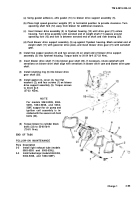
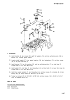
Install spring pack assembly (10) in side of governor housing (4). Using retaining nut wrench,
tighten packing nut (9).
NOT E
Torque bolts on cover (7) during engine tune-up (Para 4-4).
(6)
(7)
Install gasket (8), cover (7), two copper washers (6), and two bolts (5) on governor housing (4).
Place gasket (3) and governor cover (2)
on top of governor housing. Ensure:
control link lever (18) engages pin (19) on
differential lever (20); pin (21) in speed
control shaft enters slot in differential
lever; and, pin (22) in stop lever shaft (23)
engages between stop on underside of
cover and against vertical extension of
control link lever.
NOT E
On models 5063-5395 and
5063-539F, one governor cover
screw will be installed during in-
stallation of fuel line clip.
(8)
Para
3-20
3-21
3-22
3-19
Install governor cover (2) and seven screw
assemblies (1) on governor housing (4).
Tighten screws.
END OF TASK
FOLLOW-ON MAINTENANCE
Description
Install rocker arm covers (models
5063-5299 and 5063-5398).
Install rocker arm covers (models
5063-5392, 5063-5393, 5063-539F and
5063-539L).
Install rocker arm covers (model
5063-5395).
Install fuel line clip (models 5063-5395
and 5063-539F).
Change 1
3-99
Back to Top


