TM-9-2815-205-34 - Page 357 of 596
TM 9-2815-205-34
WARNING
(3)
(4)
If hoist and sling are not available, use two or more men to remove crankshaft.
Crankshaft is heavy and awkward to handle. Serious injury can result if
crankshaft is dropped.
CAUTION
D
O
not damage journals or main bearing shells when lowering crankshaft into position.
Damage will result in short component life.
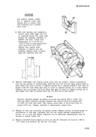
Place crankshaft (13) in upper bearing
shells in cylinder block.
Install upper crankshaft thrust washers
(5)
(6)
(7)
(15) on each side of rear main bearing
support with grooved side of thrust
washers toward crankshaft thrust
surfaces.
NOT E
•
Install bearings in same bear-
ing caps from which removed.
Ž
All crankshaft bearing shells
have a tang for proper align-
ment. Upper bearing shells
have oil holes for lubrication.
Install lower main bearing shells (11) in
bearing caps (10). Install two lower thrust
washers (12) on rear main bearing cap
with thrust washers over dowel pins in
sides of main bearing cap and grooved
side of washer facing crankshaft thrust
surface.
NOT E
Main bearing caps are bored in
position and stamped 1, 2, 3,
and 4. Install caps with identifi-
cation stamp on right side of
engine.
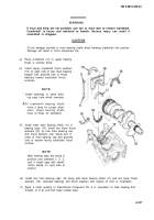
Install four main bearing caps (10) along with lower bearing shells (11) and two lower thrust
washers (12). Lubricate bearings and thrust washers with engine oil prior to installation.
Apply a small quantity of International Compound No. 2 or equivalent to main bearing bolt
threads (3 or 6) and bolt head contact area.
3-227
Back to Top


