TM-9-2815-205-34 - Page 355 of 596
TM 9-2815-205-34
(3)
(4)
(5)
Use washers, spacers, stabiliz-
ers, or supports under main
bearing bolts to prevent bolts
from bottoming out in cylinder
block holes.
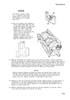
(b) With main bearings and crankshaft in
position, place plastic gage strip (23)
on crankshaft journal (24). Install main
bearing cap assembly, stabilizers or
washers, and bolts. Torque main
bearing bolts (3) to 120-130 Ib-ft
(163-177 N-m) or main bearing bolts
(6) to 53-57 Ib-ft (72-77 N.m).
Remove main bearing bolts,
stabilizers or washers, and cap
assembly. Measure width of plastic
gage with measuring strip (25).
Measure intermediate main bearing journal runout with dial indicator. Support crankshaft at
front and rear journals on inverted engine block with only front and rear upper bearing shells in
place. When high spots of runout on adjacent journals are in opposite directions, sum must not
exceed 0.003 inch total. When high spots of runout on adjacent journals are in same direction,
difference must not exceed 0.003 inch. When high spots of runout on adjacent journals are at
right angles, sum must not exceed 0.004 inch or 0.002 inch on each journal.
NOT E
Maximum clearance between connecting rod journal and bearing shell is 0.0041 inch
(with new shells). Maximum clearance between main bearing journal and bearing shell
is 0.0040 inch (with new shells). Main bearing journal taper or out-of-round must not
exceed 0.003 inch. Replace crankshaft if measurements exceed limits.
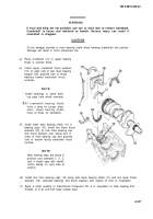
Measure all main and connecting rod bearing journals. Measure journals at several places on
circumference so that taper (calculated from two end outside diameter measurements of
journal), out of round, and bearing clearances can be determined. Measurements must be
accurate to nearest 0.0002 inch.
Measure crankshaft thrust surfaces at points (A) and (B). Dimension (A) must be 1.299 to
1.301 inches and dimension (B) must be 1.34 inches.
3-225
CAUTION
Back to Top


