TM-9-2815-205-34 - Page 358 of 596
TM 9-2815-205-34
3-53. CRANKSHAFT MAINTENANCE (Cont)
(8) For all except model 5063-5398:
(a)
(b)
(c)
(d)
(e)
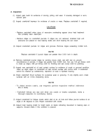
Install four stabilizer pIates (5), eight
hardened washers (4), eight large
bolts (3), eight hardened washers (2),
and eight small self-locking screws (1)
in cylinder block. Tighten bolts until
snug.
Strike main bearing caps (10) sharply
with a soft head hammer to seat caps.
Torque all main bearing bolts (3)
(except rear main bearing bolts) to
120-130 Ib-ft (163-177 N-m) in
sequence shown. Torque rear main
bearing bolts to 40-50 Ib-ft (54-68
N
.
m).
Strike both ends of crankshaft two or
three sharp blows with a soft head
hammer to ensure proper positioning
of rear main bearing cap in block
saddle. Torque all main bearing bolts
(3) to 120-130 Ib-ft (163-177 N-m)
again.
Torque eight stabilizer plate screws
(1) to 46-50 Ib-ft (62-68 N-m).
(9) For model 5063-5398:
(a)
(b)
(c)
(d)
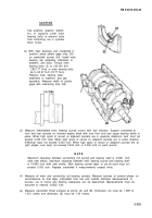
Place eight spacers (9) and four
supports (8) on main bearing caps
(10). Install eight washers (7) and
eight bolts (6) in inboard holes of
support and through spacers and
main bearing cap. Tighten bolts until
snug.
Strike main bearing caps (10) sharply
with a soft head hammer to seat them
properly.
Torque eight main bearing bolts (6) to
53-57 Ib-ft (72-77 N-m) in sequence
shown.
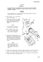
Measure gap (D) between support (8)
and bottom of cylinder block at both
ends of support. Gap must be 0.006
to 0.023 inch. If gap is not within
limits, remove and turn support over
or switch spacers (9) and measure
gap again.
3-228
Back to Top


