TM-9-2815-210-34-2-2 - Page 134 of 968
TM 9-2815-210-34-2-2
FRAME 12
1.
2.
3.
NOTE
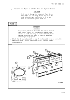
There is one oil hole (1) in camshaft front bearing
bore (2), camshaft front intermediate bearhg bore (3),
and camshaft rear intermediate bearing bore (4). There
is one oil hole in front camshaft bearing (5), front inter-
mediate camshaft bearing (6) and rear intermediate cam-
shaft bearing (7).
Mark three crankcase webs (8) with chalk or grease pencil next to oil hole
(1) in camshaft front bearing bore (2), camshaft front intermediate bearing
bore (3), and camshaft rear intermediate bearing bore (4).
CAUTION
Oil holes (1) in camshaft bearing bores (2, 3, and 4)
must line up with oil holes in camshaft bearings
(5, 6, and 7).
If oil holes do not line up, oil flow will
be blocked and camshaft bearings and camshaft will be
damaged.
NOTE
Oil hole in front camshaft bearing (5), front intermediate
camshaft bearing (6), and rear intermediate camshaft
bearing (7) is exactly at center of bearing. Because of
this, camshaft bearings (5, 6, and 7) can be put in
facing either way.
Using camshaft bushing remover and replacer kit, put in new front camshaft
bearing (5), front intermediate camshaft bearing (6), and rear intermediate
camshaft bearing (7).
Use chalk marks on crankcase webs (8) to help line
up oil hole in camshaft bearing bores (2, 3, and 4) with oil hole in camshaft
bearings (5, 6, and 7).
Do frame 9 again.
GO TO FRAME 13
4-115
Back to Top


