TM-9-2815-205-34 - Page 476 of 596
TM 9-2815-205-34
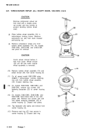
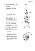
3-68. GOVERNOR REPAIR
This task covers: a. Disassembly
b. Cleaning/Inspection
c. Assembly
INITIAL SETUP
MODELS
EXPENDABLE/DURABLE SUPPLIES
All
Oil, fuel (App C, Item 27)
Sealing compound (App C, Item 44)
TOOLS AND SPECIAL TOOLS
Grease (App C, Item 18)
Tool kit, general mechanics (App B, Item 107 )
Oil, engine (App C, Item 26)
Wrench, torque (App B, Item 116)
Wood block (App C, Item 58)
Remover, bushing (App B, Item 88 )
Remover, bearing (App B, Item 87 )
EQUIPMENT CONDITION
Installer, bearing (App B, Item 63 )
Para Description
Gage, depth (App B, Item 36 )
3-31 Governor cover and spring pack removed
3-32 Governor removed from blower assembly
MATERIALS/PARTS
1
Plug (App F, Item 122)
1
Plug, expansion (App F, Item 128)
1
Seal, special (App F, Item 176)
1
Packing, preformed (App F, Item 113)
a. Disassembly
NOT E
Before disassembly of gover-
nor, clean entire unit and
inspect for worn or damaged
parts. Repair damaged parts
without disassembly of gover-
nor wherever possible.
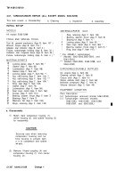
(1) Governor cover
(a)
(b)
(c)
(d)
(e)
(f)
Loosen screw (1) and remove remote
control lever (2).
On model 5063-5398, remove spacer
(3) from throttle shaft (4).
Remove flat washer (5) from throttle
shaft (4).
Remove retaining ring (6), flat washer
(7), and shouldered washer (8) and
withdraw throttle shaft (4) from bottom
of cover (9).
Remove preformed packing (10) from
cover (9). Discard packing.
Loosen screw (11) and remove stop
lever (12).
3-348
Back to Top


