TM-9-2815-213-34 - Page 76 of 192
*TM 9-2815-213-34
(3) Apply thin coat of high pressure lubri-
cant and press bushing flush into housing bore
using arbor press.
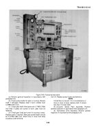
(4) Attach fuel pump fixture (42, fig. B-28)
as shown in figure 3-86.
(5) Line ream bushing to 0.7495/0.7505
inch.
3-106. Assembly of Sub-Assemblies and
pump
a.
Pump Housing.
(1) Install all pipe plugs, dowels, and clips
using new O-Rings as required.
(2) Assemble throttle assembly in reverse
order of disassembly (para. 3-102.b. (3)), in-
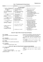
stalling new 0 Ring with O-Ring assembly tool (37,
fig. B-28) as shown in figure 3-87.
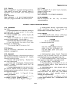
(3) Install throttle assembly as shown in
figure 3-88.
(4) Install compression spring and assemble
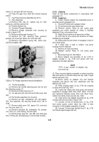
Figure 3-85. Scribing governor barrel.
Figure 3-86. Reaming mainshaft bushing.
governor plunger. Assembled in reverse order of
(para. 3-102.b. (2)).
(5) Insure clearance between thrust washer
and drive plunger governor as shown in figure
3-89.
(6) Install governor plunger assembly as
shown in figure 3-78.
(7) Install new filter assembly. Assemble in
reverse order of disassembly (para. 3102,
b. (1)).
b.
Tachometer Drive Assembly
. Assemble in re.
verse order of disassembly (para. 3-102.a. (7)).
c.
Governor Spring Pack Assembly
. Assemble
in reverse order of disassembly (para. 3-102.a.
(6)).
d.
Fuel Pump Gear
. Assemble in reverse order
of disassembly (para. 3-102.a. (5)) insuring that
notches in housing and cover correspond.
e.
Mainshaft Cover and Governor Assembly
.
Figure 3-87. Throttle shaft O-ring installation.
Figure 3-88. Throttle assembly installation.
3-47
Back to Top


