TM-9-2815-213-34 - Page 81 of 192
*TM 9-2815-213-34
Chart
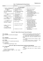
4.-Troublsshooting Fuel Pump Continued
Malfunction
Probable cause
Corrective action
FUEL PUMP ASSEMBLY
4.
The 40 p.s.i.
checkpoint cannot be
a
.
Governor plunger has wrong chamfer
a
.
Replace plunger with correct chafer
obtained within
specified maxi
or has a worn chamfer.
mum speed limits
b
.
Governor barrel and plunger in
b
.
Refit governor barrel to accept a
NOTE
correct Aft.
plunger two classes larger.
"Governor setting 3020 to 3040
c
.
Governor torque spring incorrect.
c
.
Install correct spring.
rpm"
is 40 psi manifold pressure
d
.
Governor weight incorrect or weight
d
.
Install correct weights Make weight
is specified.
assist setting incorrect.
assist setting 0.890/0.910-inch and
46 to 54 psi e 800 rpm for V8-300 engine pump.
5.
Throttle leakage is above specified.
a
.
Throttle shaft scored or incorrect
a
.
Install new throttle shaft (standard
NOTE
fit in throttle sleeve.
or oversize) and lap to fit.
The permissible throttle leak
b
.
Governor plunger incorrect fit in
b
.
Install new governor plunger (standard
age Is 3ce.
governor barrel.
or oversize) and lap to fit.
6.
Incorrect fuel manifold pressure.
a
.
Incorrect idle plunger (button) or
a
Install new idle plunger.
NOTE
surface finish is rough.
Fuel manifold pressure should
b
.
Gear pump fails to pump 850 pounds
b
.
Install new gear pump.
be 227 psi
6
3000 rpm.
o
f fuel per hour at 2100 rpm.
c
.
Wrong throttle restriction.
c
.
Set
throttle restriction at correct value
7.
Incorrect check point pressure.
a
.
Idle plunger rough or has void &
a
.
Polish surface with oilstone or re-
NOTE
place with like or serviceable part.
Checkpoint pressure should be
b
.
800 rpm checkpoint.
b
.
Check 800 rpm
checkpoint under
165 to 170 p.s.i
at 2500 rpm.
malfunction No.
8 to be sure it is
within specifications before proceeding.
c
.
Incorrect torque or governor spring.
c
.
Remove front cover and check for
proper torque or governor spring.
8.
800 rpm checkpoint out of
a
.
Checkpoint pressure is too low.
a
.
If weight assist protrusion is within
specification.
specification (0.890 to 0.910 inch)
NOTE
one or more shims may be added
The desired checkpoint pres-
to the assembly to obtain the
sure at 800 rpm is 46 to
p54.
desired pressure.
b
.
Checkpoint pressure is too high.
b
.
Remove weight assist shims
required to
decrease pressure.
Section XX.
Repair of Water Crossover Pipe and Lifting Eyes
3-110.
Cleaning
Clean components in accordance with paragraph
2-5.
3-111.
Inspection
Refer to paragraph 26 for inspection procedure
3-112.
Repair
Refer to paragraph 2-7 for general repair procedures.
3-113.
Installation
a
. Position (rear) engine lifting eye,
water
connection and new gaskets to right bank cylinder head
(fig.
210).
Secure with lockwashers and cap screws.
b
.
Position water connection with new gasket to left
bank cylinder head.
Secure with lockwashers and cap
screws.
c.
Install new water hose and clamps on water
crossover pipe.
d
.
Position crossover pipe to connections.
Place
hose in position and secure with hose clamps.
.
Section XXI.
Repair of Air Intake Preheater Assembly and Intake Manifolds
3-114.
Disassembly
(fig.
B-20).
a.
Remove hoses from assembly.
b.
Remove preheater adapter (2) from cleaner
assembly connection.
c.
Remove nozzle (6) and key washer (5) from
adapter.
d
. Remove glow plug from air cleaner assembly
connection.
3-52
Back to Top


