TM-9-2815-213-34 - Page 82 of 192
*TM 9-2815-213-34
3-115.
Cleaning
Refer to paragraph 2-5 for general cleaning procedures.
Clean adapter and nozzle with carburetor cleaner or
equivalent.
Insure that nozzle screen and spray holes
are open.
3-116.
Inspection
Refer to paragraph 2-6 for general inspect procedures.
Check glow plug operation with a vdc source of power.
3-117.
Repair
Refer to paragraph 27 for general repair procedures.
Replace all defective parts.
3-118.
Assembly
Refer to paragraph 3114 and reverse procedures.
3-119.
Installation
Refer to paragraph 2-10.i.,
and 2-lO.j.,
and reverse
removal procedures.
Section XXII.
Repair
of Water Pump Assembly
3-120.
Disassembly
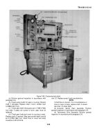
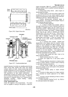
(fig.
B-22).
a
. Remove large snap ring from pump housing by
reaching through the access ports in the drive pulley,
with a pair of snap ring pliers.
b.
Using a suitable puller,
pull the impeller (18)
from the drive shaft.
c
. Press on impeller end of shaft to remove
assembly from pump body.
Press out bear (11).
d
. Remove carbon face seal (15) from pump body.
e.
Press shaft through drive pulley (3) and large
bearing (8).
Lift off spacer (9).
f.
Remove snap ring (10) from groove shaft.
3-121.Cleaning
Clean all components in accordance with instructions
contained in paragraph 2-7.
3-122.
Inspection
Perform general inspection of all component accordance
with instructions contained in pa graph 2-7.
Specific
inspection procedures follow.
a
. Inspect water pump bearings.
Replace those
with rough or worn races.
b
. Inspect water pump impeller.
Replace impeller
assembly if cracked or corroded to extent that it will
interfere with circulation.
c
. Replace impeller assembly if the minimum 0.001
inch press-fit between shaft and impeller exceeded.
Measure impeller bore and shaft side diameter to project
this minimum allowance
d.
Inspect water pump mounting parts damage.
Replace as necessary.
e
. Examine carbon seal carefully to make sure it is
not cracked or chipped.
Replace if necessary
f
. Inspect silicone oil seal.
Replace if damaged
g.
Inspect ceramic seal seat that is bonded to the
impeller counterbore (vane side) for damage and
excessive wear.
Replace if seal is damaged.
3-123.
Assembly
a.
Lubricate shaft outside diameter and bearings
inside diameter with multipurpose industrial grease.
CAUTION
Do not use lead base sealer.
b
.
Pack bearings with GAA.
NOTE
One piece sealed bearing must be in-
stalled on the shaft and pressed in the
body with BLACK shield to the pulley
end of the shaft.
c
. Install snap ring in groove of shaft.
Press inner
bearing on shaft with shielded side out to ward impeller
end of shaft until inner race seats against snap ring.
d.
Position shaft and bearing in bore of pump body.
Slide spacer over shaft seating on shoulder of shaft.
e.
Fill cavity of bore 1 to % full of GAA.
f.
Place large bearing over shaft and into bore of
housing with shielded side out.
Press bearing into its
seat in the housing bore.
g. Install large snap ring in bore of pump body to
secure bearings in place.
h. Support shaft on impeller end and press on
pulley fixed sheave until sheave hub is tight against
bearing inner race.
Attach adjustable sheave to
complete the pulley installation.
i.
Turn water pump body assembly over and press
in a new carbon face seal using a suitable mandrel and
pressing arbor.
3-53
Back to Top


