TM-9-2350-260-20-1-3 - Page 446 of 783
TM 9-2350-260-20-1-3
SHIFT LINKAGE ADJUSTMENT (Sheet 14 of 20)
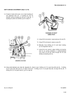
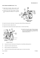
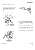
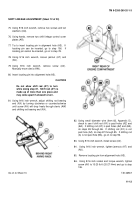
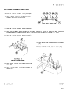
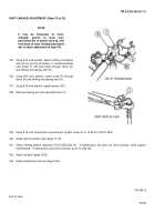
98. Using 9/16 inch wrench, install screw (BB) through
clevis (AH) and shifting rod bearing end (BC.
99. Using 9/16 inch wrench, tighten jamnut (AU).
100. Using 9/16 inch socket and torque wrench, tighten
screw (BB) to 15-20 lb-ft (20-27 N
•
m).
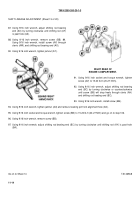
RIGHT REAR OF
ENGINE COMPARTMENT
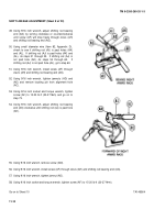
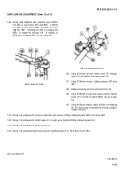
103. Using 9/16 inch wrench, tighten jamnut (AT).
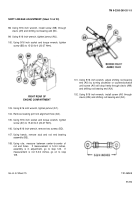
104. Remove locating pin from alignment hole (AS).
105. Using 9/16 inch socket and torque wrench, tighten
screw (AV) to 15-20 lb-ft (20-27 N
•
m).
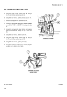
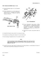
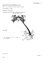
106. Using 9/16 inch wrench, remove two screws (BD).
107. Using hands, remove stud and rod end bearing
assembly (BE).
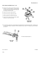
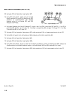
108. Using rule, measure between center-to-center of
rod end holes.
If measurement is 5-3/4 inches,
assembly is in adjustment, go to step 123.
If
measurement is not 5-3/4 inches, go on to step
109.
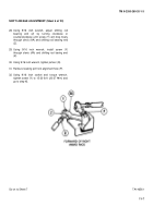
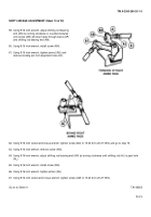
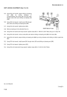
101. Using 9/16 inch wrench, adjust shifting rod bearing
end (AX) by turning clockwise or counterclockwise
until screw (AV) will drop freely through clevis (AW)
and shifting rod bearing end (AX).
102. Using 9/16 inch wrench, install screw (AV) through
clevis (AW) and shifting rod bearing end (AX).
Go on to Sheet 15
TA146569
11-15
Back to Top

