TM-9-2350-260-20-1-3 - Page 444 of 783
TM 9-2350-260-20-1-3
SHIFT LINKAGE ADJUSTMENT (Sheet 12 of 20)
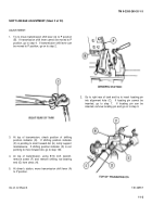
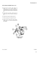
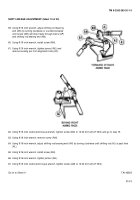
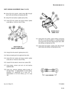
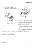
75. Using 9/16 inch wrench, remove five screws and ten
washers (AQ).
76. Using hands, remove two shift linkage control cover
plates (AR).
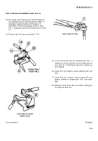
77. Try to insert locating pin in alignment hole (AS).
If
locating pin can be inserted, go to step 106.
If
locating pin cannot be inserted, go on to step 78.
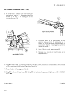
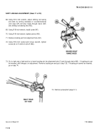
78. Using 9/16 inch wrench, loosen jamnut (AT) and
(AU).
79. Using 9/16 inch wrench, remove screw (AV).
Manually move clevis (AW).
80. Insert locating pin into alignment hole (AS).
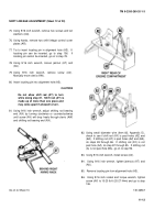
CAUTION
Do not allow shift rod (AY) to turn
while doing step 81.
Shift rod (AY) is
made up of more than one piece and
may come apart if allowed to turn.
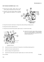
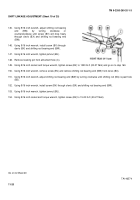
81. Using 9/16 inch wrench, adjust shifting rod bearing
end (AX) by turning clockwise or counterclockwise
until screw (AV) will drop freely through clevis (AW)
and shifting rod bearing end (AX).
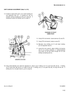
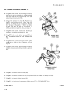
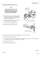
82. Using small diameter wire (Item 82, Appendix D),
check to see if shift rod (AY) is past holes (AZ) and
(BA).
If shifting rod (AY) is past holes (AZ) and (BA),
do steps 83 through 86.
If shifting rod (AY) is not
past hole (AZ), do step 87 through 95.
If shifting rod
(A) is not past hole (BA), go on to step 96.
83.
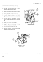
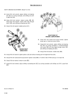
Using 9/16 inch wrench, install screw (AV).
84.
Using 9/16 inch wrench, tighten jamnuts (AT) and
(AU).
85.
Remove locating pin from alignment hole (AS).
86.
Using 9/16 inch socket and torque wrench, tighten
screw (AV) to 15-20 lb-ft (20-27 N
•
m) and go to step
106.
Go on to Sheet 13
TA146567
11-13
Back to Top

