TM-9-2815-205-34 - Page 59 of 596
TM 9-2815-205-34
2-14. OIL FILTER ASSEMBLY, ADAPTOR, AND MOUNTING BRACKETS REMOVAL/
lNSTALLATION (MODELS 5063-5396 AND 5063-539F) (Cont)
(5)
(6)
(7)
(8)
(9)
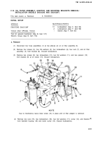
Remove two hose assemblies (1) from two elbows (19) on oil filter adaptor (20).
Disconnect turbocharger oil supply hose (21) from elbow (22) in oil filter adaptor (20).
If necessary, remove two elbows (19) from oil filter adaptor (20).
Remove four screws (23), four Iockwashers (24), and four flat washers (25) from oil filter
adaptor (20) at rear left side of cylinder block. Discard Iockwashers.
Remove oil filter adaptor (20) and gasket (26) by tapping with a soft head hammer to break
seal. Remove lower screw (14) and discard gasket.
b. Installation
(1)
(2)
(3)
(4)
(5)
2-32
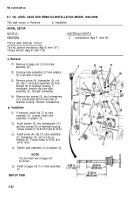
Install screw (14) in flywheel housing prior to installation of oil filter adaptor due to interference.
Install gasket (26), oil filter adaptor (20), four flat washers (25), four Iockwashers (24), and four
screws (23) on rear left side of cylinder block. Torque screws to 30-35 Ib-ft (41-47 N·m).
If removed, install two elbows (19) in oil filter adaptor (20). Tighten elbows securely with ends
down.
Connect two hose assemblies (1) to two elbows (19) on oil filter adaptor (20). Tighten securely.
Connect oil supply hose (21) to elbow (22) in oil filter adaptor (20). Tighten securely.
Back to Top


