TM-9-2815-205-34 - Page 67 of 596
TM 9-2815-205-34
2-17. ENGINE/TRANSMISSION OIL COOLER REMOVAL/INSTALLATION (MODEL 5063-5392)
(Cont)
(5)
(6)
(7)
(8)
(9)
(10)
(11)
(12)
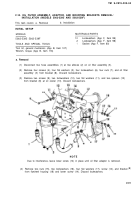
Install four flat washers (13), four Iockwashers (12), two short bolts (10) with lower rear bolt
through clip (14), and two long bolts (11) in oil cooler assembly (3). Remove two guide studs
(21) and install remaining two flat washers (13), two Iockwashers (12), and two long bolts (11).
If removed, install pipe plug (9) in elbow (7). If removed, install clip (5) on air box heater fuel
line (31).
NOT E
Front bolt (4) is installed through clip (5), on fuel line (31), into elbow (7).
Slide elbow (7) into hose (2) and install gasket (8), elbow (7), two Iockwashers (6), and two
bolts (4) on cylinder block. Torque bolts to 13-17 Ib-ft (18-23 N·m).
Adjust hose (2) and two clamps (1) between elbow (7) and oil cooler assembly (3) with clamp
adjusting screws facing front of engine. Tighten clamps securely.
END OF TASK
FOLLOW-ON MAINTENANCE
Para Description
2-6 Install coolant pump.
2-12 Install oil filter adaptor.
2-40
Install three long studs (21) and short
stud (22) on oil cooler assembly (3).
Install four flat washers (17), four
lockwashers (16), and four nuts (15) on
studs (21 and 22).
Torque two bolts (10) and four bolts (11)
to 13-17 lb-ft 918-23 N
.
m). Torque four
nuts (15) to 15-19 lb-ft (20-26 N
.
m).
Slide hose (2) and two clamps 91) onto
oil cooler assembly (3).
Back to Top


