TM-9-2815-205-34 - Page 62 of 596
TM9-2815-205-34
2-15. OIL FILTER ASSEMBLY AND ADAPTOR REMOVAL/lNSTALLATION (MODEL 5063-5398)
This task covers: a. Removal
b. Installation
INITIAL SETUP
MODELS
MATERIALS/PARTS
5063-5398
8
Lockwashers (App F, Item 99)
1
Gasket (App F, Item 49)
TOOLS AND SPECIAL TOOLS
1
Gasket (App F, Item 56)
Tool kit, general mechanics (App B, Item 107 )
Wrench, torque (App B, Item 116 )
a. Removal
(1)
(2)
(3)
(4)
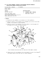
Disconnect turbocharger oil supply hose (1) at elbow (2) in oil filter and adaptor assembly (3).
Remove four screws (4), four Iockwashers (5), four flat washers (6), oil filter and adaptor
assembly (3), and gasket (7) from rear left cylinder block. Discard Iockwashers and gasket.
Remove four screws (8), four Iockwashers (9), four flat washers (10), oil filter assembly (11),
and gasket (12) from adaptor (13). Discard gasket and Iockwashers.
If engine is out of container, remove in-place screw (14) from flywheel housing.
b. Installation
(1)
(2)
(3)
(4)
If engine is out of container, install screw (14) in flywheel housing.
Install gasket (12), oil filter assembly (11), four flat washers (10), four Iockwashers (9), and four
screws (8) on adaptor (13). Torque screws to 30-35 Ib-ft (41-47 N·m).
Install gasket (7), oil filter and adaptor assembly (3), four flat washers (6), four Iockwashers (5),
and four screws (4) on rear left cylinder block. Torque screws to 30-35 Ib-ft (41-47 N-m).
Connect turbocharger oil supply hose (1) to elbow (2) in oil filter and adaptor assembly (3).
Tighten hose connection securely.
END OF TASK
2-34
Back to Top


