TM-9-2815-205-34 - Page 58 of 596
2-14. OIL FILTER ASSEMBLY, ADAPTOR, AND MOUNTING BRACKETS REMOVAL/
INSTALLATION (MODELS 5063-5395 AND 5063-539F)
This task covers: a. Removal
b. Installation
INITIAL SETUP
MODELS
MATERIALS/PARTS
5063-5395 5063-539F
10
Lockwashers (App F, Item 99)
2
Lockwashers (App F, Item 98)
TOOLS AND SPECIAL TOOLS
1
Gasket (App F, Item 60)
Tool kit, general mechanics (App B, Item 107)
Wrench, torque (App B, Item 116)
a. Removal
(1)
(2)
(3)
(4)
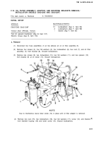
Disconnect two hose assemblies (1) at two elbows (2) on oil filter assembly (3).
Remove four screws (4), four flat washers (5), four Iockwashers (6), four nuts (7), and oil filter
assembly (3) from bracket (8). Discard Iockwashers.
Remove two screws (9), two Iockwashers (10), two flat washers (11), and two spacers (12)
from bracket (8) at oil cooler (13). Discard Iockwashers.
NOT E
Due to interference, leave lower screw (14) in place until oil filter adaptor is removed.
Remove two nuts (15), two Iockwashers (16), four flat washers (17), screw (14), and bracket
from flywheel housing (18) and lower screw (14). Discard Iockwashers.
(8)
2-31
TM 9-2815-205-34
Back to Top


